Those who have ever been to our apartment know that we have a broken entrance intercom. I do remember it was working (though the previous tenants said it could not open the door so you had to run all the way down from the fourth floor) but one day it just stopped.
First thing you do when such a thing breaks ? You call your landlord. Once. Twice. You get bored, and just tell people to call you because the doorbell is broken. You re-sign the contract because some of the old tenants are moving out (the place we are at was a share), and reminding the landlord about the doorbell, he promises to fix it. You remind him. He finally sends the repair man who spends half a day scratching his head with zero results.
Finally you buy a radio-controlled doorbell and call it a day. Until you discover the damn thing periodically hangs, that is - so even after all this time, there is *still* no reliable way for someone to ring you from downstairs.
Finally, I said: "Enough. Let's see how this beast functions. It can't be that difficult to fix it, can it ?"
That's how this endeavour started.
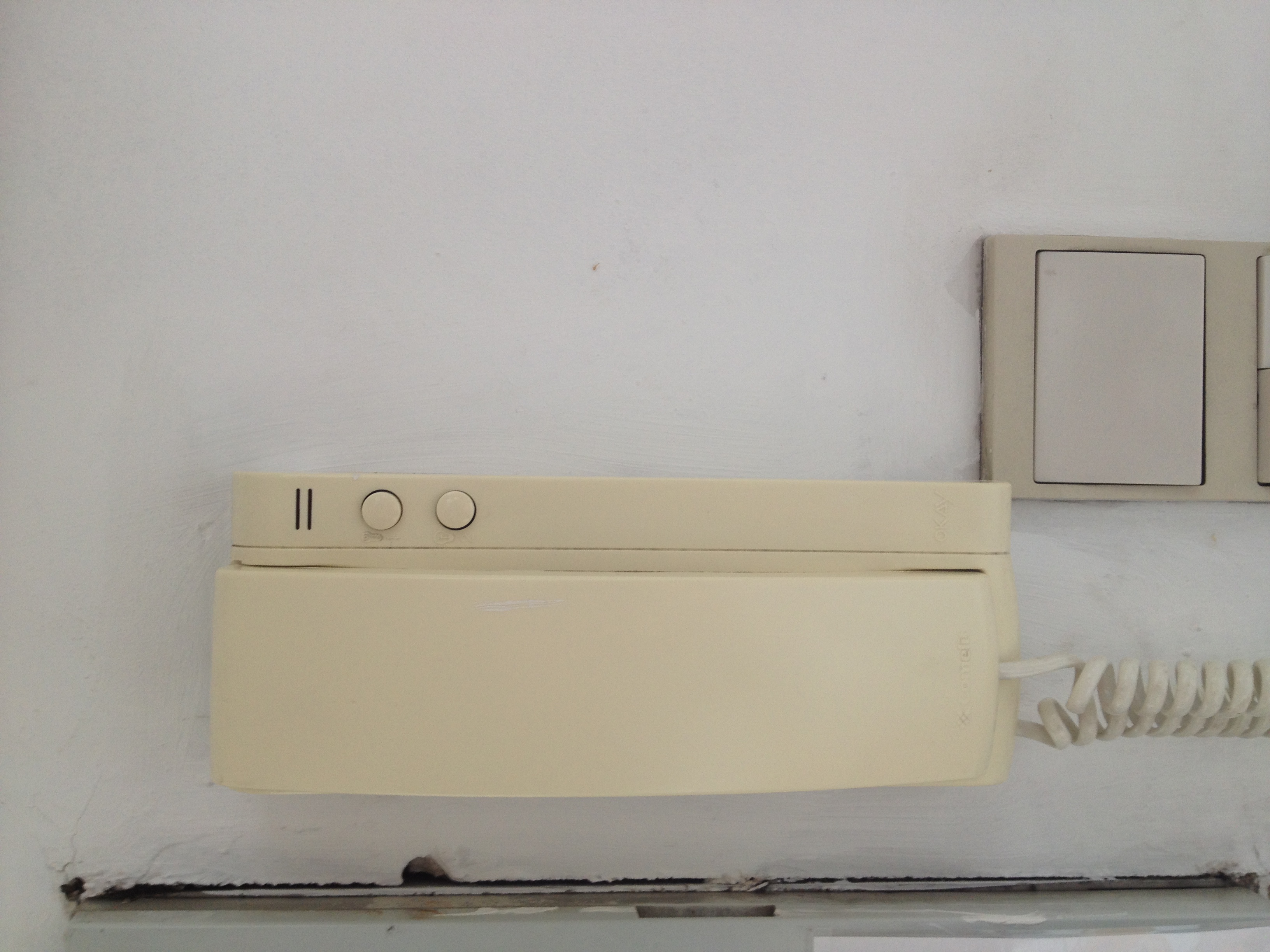
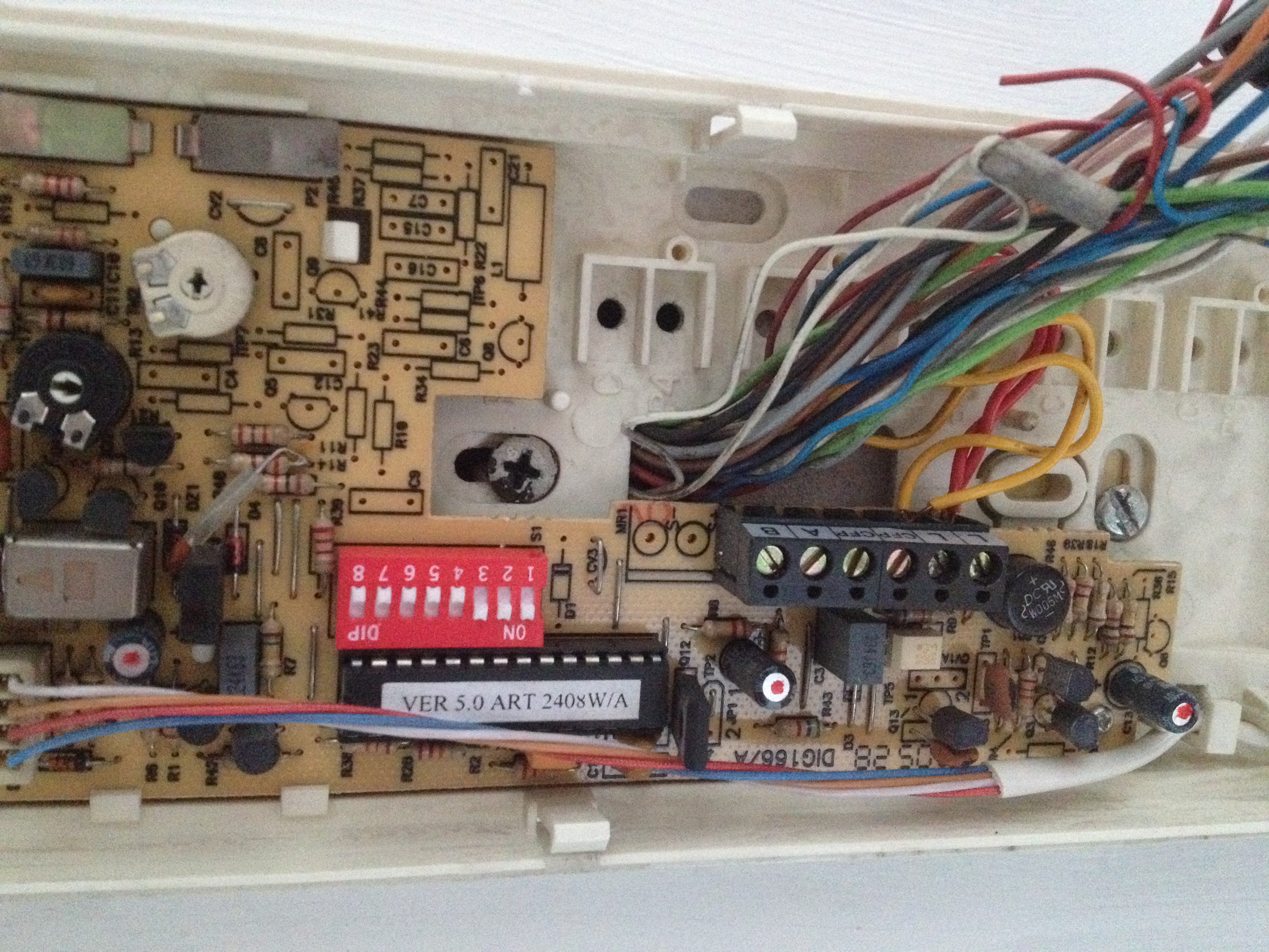
First step: approach the subject of intervention (picture here) and remove the cover. This reveals the following:
First impressions: wow, there's only two wires! So, this thing *has* to be digital. This may be a blessing or the curse. The DIP switch seems to be set to position "7", which, considering there are 6 apartments below, is probably something like a "subscriber ID". The wires have about 28V DC between them - so this is both power and signaling bus. Clever! Let's see what the "2408W/A" will tell us. Putting it into search and we arrive indeed to a unit called "2408W/A" made by Comelit. Oh, the headset also has "Comelit" engraved on it. So I must be on the right track!
There are two fairly crudely-made contacts - one for the "unlock" button, and the other for the "light" button. Reportedly, "unlock" had never worked - but, when I short the contacts of it, I can hear some bleeping from the headset. A trip downstairs reveals that the keypress had indeed opened the door! Yay! I've been told it does not work.
This is half of the problem solved - unfortunately - it's the wrong half of the problem! It's nice to be able to open the door remotely, but you need to know when! Let's see if we can reanimate the doorbell function.
Unfortunately, the datasheet is not telling anything useful - though, maybe, that the two-wire connection is called "Simplebus". The bus is proprietary, so the search is useless. Let's dive into the drawer and see what toolkit can I come up with to analyze this.
The first item to investigate is very simple: Can I detect anything on the bus when I press the call button downstairs ?
To test this, I start with a very simple assumption: given this is a two-wire bus, it has to have the AC component in it for activity. This means an appropriately powered LED might be a good first shot. A back-of-the-envelope estimate reveals I'd need 10KOhm and 1KOhm in series - and connect the LED to the 1KOhm one, this should give about 2.5V at 2.5mA (= 28V/11000Ohm) which should be just about perfect for the red LED. Let's make it!
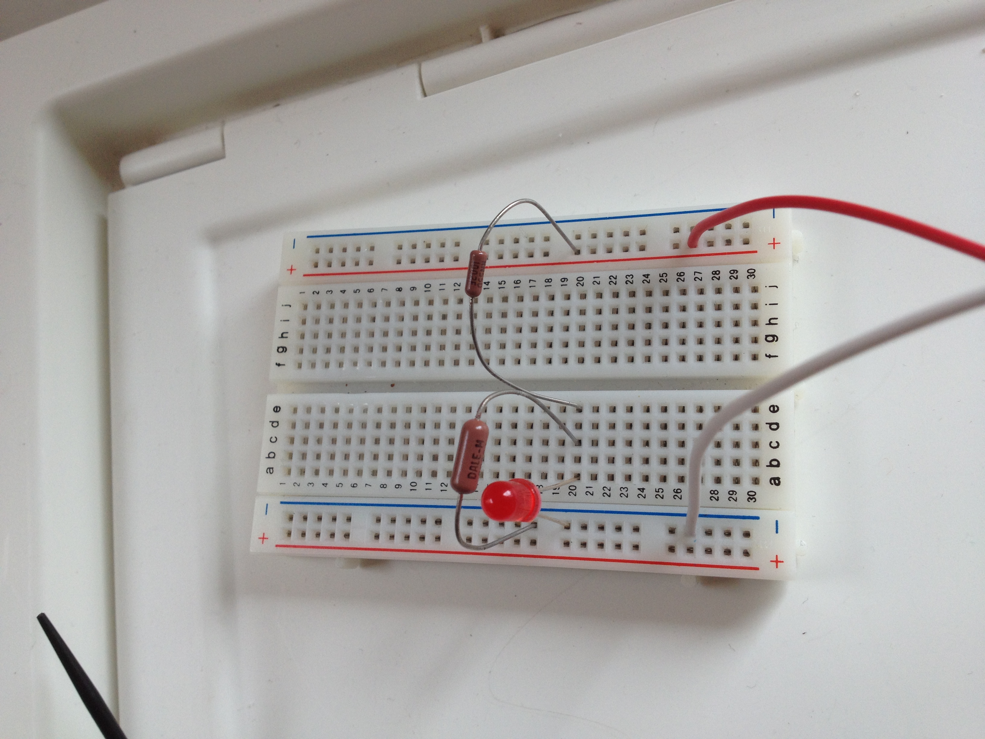
A test with the "light" button reveals indeed some flickering. Time to go downstairs and try calling from the entrance! (This is where the props go to my lovely girlfriend Eimear - who was very kind to interrupt what she was doing and look at the LEDs while I was pressing the buttons).
Now, 2.5V is a pretty good approximation for the logical one in TTL logic - why not gamble and try attaching the logic analyzer directly ? So I pull out my Saleae Logic and try it out. The results are mixed - when I press the "light" or "lock" buttons, I can see the clear pattern of signals, at about 110baud, but when I run downstairs, I see nothing. Just a couple of spikes. So, they actually do use the modulation... So, I need to look further at the circuit itself, and maybe tap there.
The 28-pin DIP chip with the "VER 5.0 2408W/A" label on it draws my attention - I've been playing with ATMEGA mictrocontrollers a lot, and it is the same form-factor. Could it be that this device is microcontroller-driven ? Let's remove the label (given that the repairman could not fix it, I am not too worried about the warranty). The marking is very faded out and the only thing I can see clearly in the end is the digit "3" at the end of the marking, but with some more searching I find a thread in the forum in French which talks about the same brand having PIC16F73 controllers. I've never worked with them, but I'm not interested in programming this time - I want to see if I can find the "digital in", so I could use the logic analyzer to see what is going on the wire. Let's remove the PCB from the cover and look closer... Below is the picture with the PIC pins annotated, as well as my imaginary line between what I think is the "modem" (analog part for diving the bus) and the "local smarts" (the digital microcontroller-based circuitry as well as the handset attachments).
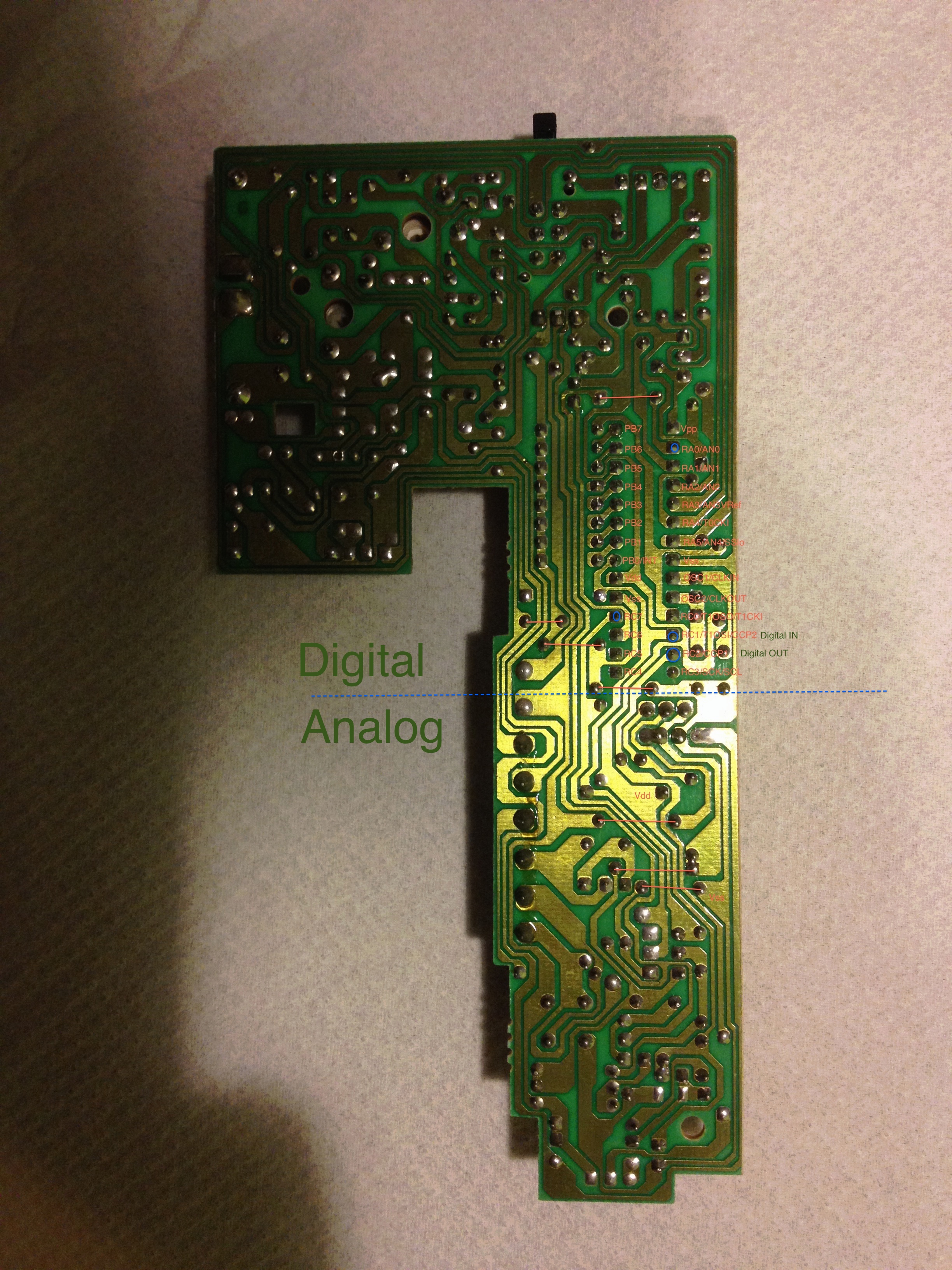
I decide on a very simple approach: attach the analyzer to the microcontroller pins which I can trace on the PCB to connect to the "Analog" world and see what happens. These are the pins marked with blue circles.
Now, with logic analyzer connected, let's press the "light" button, and hurray! There is something:
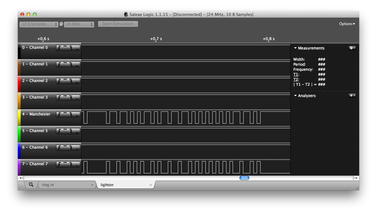
Before being too happy, let's run down and press the call button for my floor:
And now with some zoom:
Whoa! This is great. The signals do look very similar, and also seems I have tapped both the "input" from the bus (the yellow wire on Logic analyzer) and the "output" to the bus from my unit (the violet wire).
This is something I can work with! The initial look suggests there is a negative pulse starting to probably wake up or warm-up the receiver units, and then go the modulated bits. Seems like each bit is preceded by a negative pulse, and then one value is coded as a short positive pulse, and the other by a long positive pulse. Let's assume long one is one and the short one is zero, and decode the commands...
light on:
1 1 0 0 1 0 1 1 1 0 0 0 0 0 0 1 1 0

lock open:
0 0 0 0 1 0 1 1 1 0 0 0 0 0 0 0 1 0

call from downstairs:
0 0 0 0 1 1 0 1 0 1 0 1 0 1 0 1 1 0
Remembering that the 8-DIP switch was set to a value "7", we can try to make some conclusions from this. Seems like the first 6 bits are dedicated to the command, then goes the address and then go additional four bits (checksum?). Let's try to set the DIP switch into a position of "127" and compare the results:
light on:
1 1 0 0 1 0    1 1 1 0 0 0 0 0  0 1 1 0

lock open:
0 0 0 0 1 0    1 1 1 0 0 0 0 0  0 0 1 0

call from downstairs:
0 0 0 0 1 1    0 1 0 1 0 1 0 1  0 1 1 0

light on with DIP switch in all-ones-but-1:
1 1 0 0 1 0    1 1 1 1 1 1 1 0  0 1 0 1
This is not bad at all! Also, this allows to guess the algorithm for the four bits of checksum: they simply count the number of logical ones in the previous 14 bits! But what's the deal with calling ? The number is by far not 7!
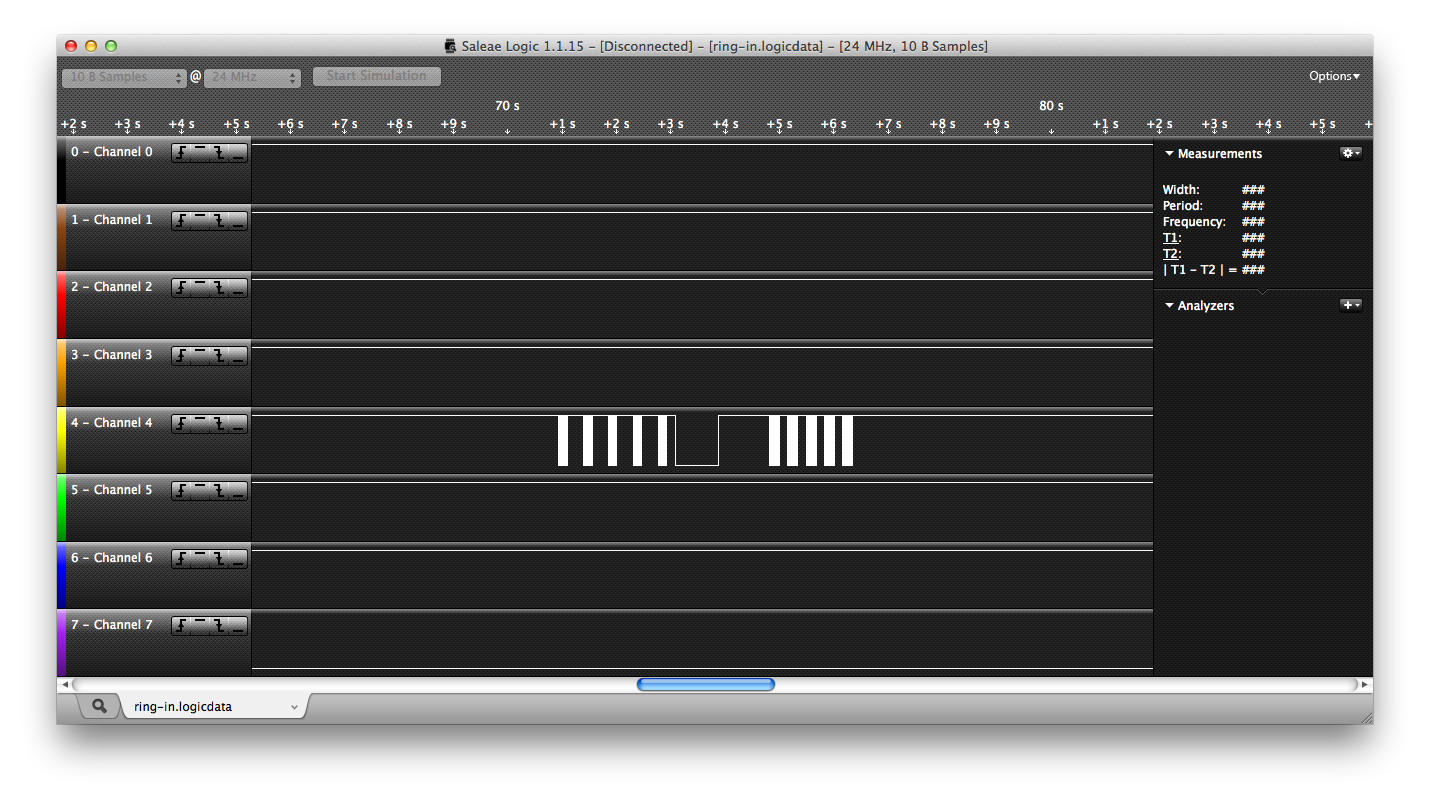
Luckily for me, the very first apartment downstairs is not rented out at the moment, so I could doublecheck both the protocol behavior as well as the bitwise contents. Here is how it looks at birds-eye view:
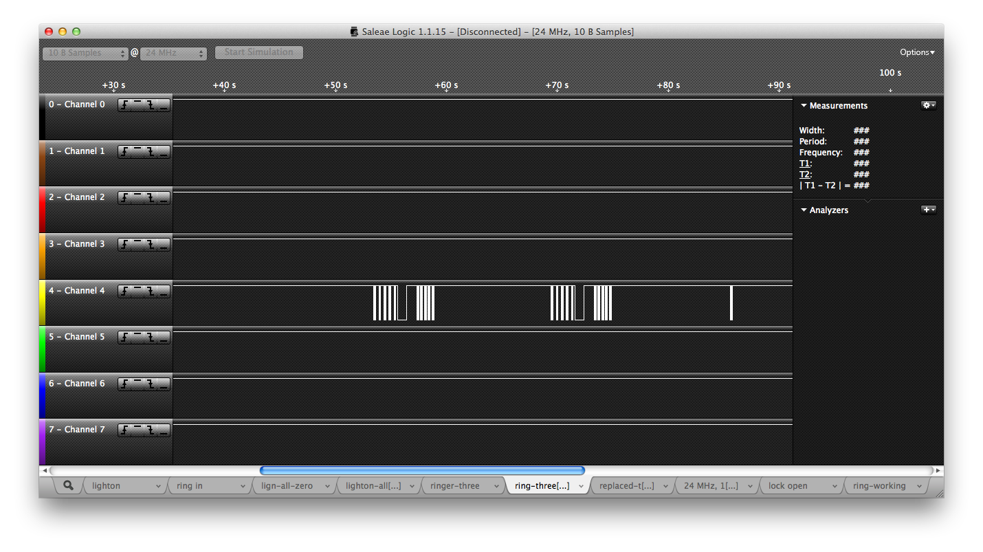
I tried my own call buttons twice (no visible reaction), and then tried the first floor's apartment button - which immediately caused the "ring-ring" sound in the intercom panel. Probably the unit which recognizes its message needs to signal something back ? And indeed this is the case:

The unit which recognizes the message to it, sends the three zeroes back. (Upon looking closer at the signature of the "unlock door" from my unit, indeed - the lock confirms the reception of command in the same way!) That's why the non-working signal repeats five times - it is retransmitting!
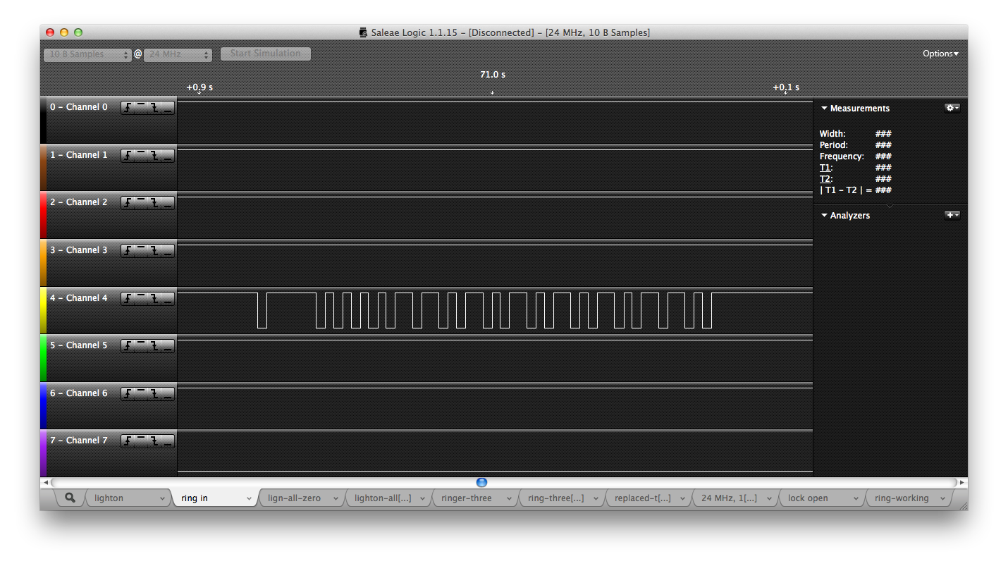
From the bitwise content standpoint, this ring vs. my ring looks like:
my non-working call from downstairs:
0 0 0 0 1 1    0 1 0 1 0 1 0 1  0 1 1 0

1st floor working call from downstairs:
0 0 0 0 1 1    1 0 0 0 0 0 0 0  1 1 0 0
You can see the semantics are preserved - the command to call is 000011, and the last four bits are the checksum, and the first floor apartment's number is 1 ! This starts to look more and more like somehow the intercom's brain had a stroke - and my doorbell's number was the victim !
One last test: put the DIP switch on my doorbell into position "1" and go ring to the first floor from downstairs - and my doorbell responds to that!
So, now the theory has been almost confirmed - the final confirmation is after reprogramming the DIP switch on my unit to "01010101" and going downstairs to check... and behold, it works! With bidirectional audio, as well! (Audio goes over the same two-wire bus, it seems - which is quite amazing in itself, but since it works fine I did not have the need to explore it).
This is the happy-end of the story - now with a functioning doorbell, intercom phone, and the door opener. Civilization!
Just need to print the name label.
../
docs/                                              01-Jul-2024 21:41                   -
lock-timings/                                      01-Jul-2024 21:41                   -
logic-files/                                       01-Jul-2024 21:41                   -
ring-timings/                                      01-Jul-2024 21:41                   -
HEADER.txt                                         01-Jul-2024 21:41               10260
breadboard1.JPG                                    01-Jul-2024 21:41             2129746
breadboard2.JPG                                    01-Jul-2024 21:41             2223744
comm-no-cover.JPG                                  01-Jul-2024 21:41             3137699
communicator.JPG                                   01-Jul-2024 21:41             1903114
digital-input-when-ring.png                        01-Jul-2024 21:41              156760
light-button-pressed.png                           01-Jul-2024 21:41              153471
nonworking-ring-and-working-ring.png               01-Jul-2024 21:41              182377
pcb-with-annotations.JPG                           01-Jul-2024 21:41             2832029
ring-mine-zoom.png                                 01-Jul-2024 21:41              179190
ring-others-zoom.png                               01-Jul-2024 21:41              178370
ring-pressed.png                                   01-Jul-2024 21:41              178801
ring-working.png                                   01-Jul-2024 21:41              170409